 |
 |
|
|
 |
|
Generally speaking, this is the technically clean solution: a RasPi in the PEB, its own power supply and direct connection to the net via LAN cable. And now the "but"s are coming... On the one hand, there is the price of the board itself (USD 139.99), plus the exorbitant shipping costs (USD 44.43), and then also the customs plus VAT and handling costs (EUR 45,33). In the end, almost EUR 205,- came together - of course without the Pi 3B+, which cost another EUR 45,- - totally so EUR 250,-!! And this is for a solution that does not even include the 32K memory expansion. Well - I wanted it that way... 😉 And fairly, it is also necessary to note that it is very difficult to acquire hardware today for projects that are either hardly in demand or are no longer supported by the "inventor". But it is not up to SW support in this case - the last DSR update is just under half a year old. Be that as it may, I ordered this board from the Brewing Academy, where you have a very special relationship to the indication "in stock". In addition, they found it opportune to place a really extremely ugly logo on the silk print, which of course had to be erased before the first pictures could be taken. Well, it doesn't matter - as long as this thing was available and arrived at some point. But I was a bit shocked when I held the parcel in my hands - "repackaged by the post office to check the content for dangerous items" and a - unreadable - signature. Hey people - the thing didn't go to the country 404!!! Well, the card was still in it, even if outside of the bubble wrap, the invoice somewhat crumpled and the whole thing was quite unprofessionally taped... At this point in time, I cannot ensure that the card works, because the 32K has to go to the Atronic FDC before, but that is still in the making. | |||
The board itself... | |||
| The board looks very good overall - the traces are smooth, cleanly laminated, the silk print resistant to solvent and acid, the VIAs sit perfectly in the middle and the solder joints on the top are perfect. There are 2 supply networks, one with 5V for bus interface, 3-to-8 decoder (you serious? Why do we have a CPLD?), EPROM (yes - E PROM, no EEPROM) and LED, which is mounted 90° twisted... - as well as a 3.3V network for CPLD and JTAG. Further at the discussion of the power supply further down - meanwhile, here is the schematic. | 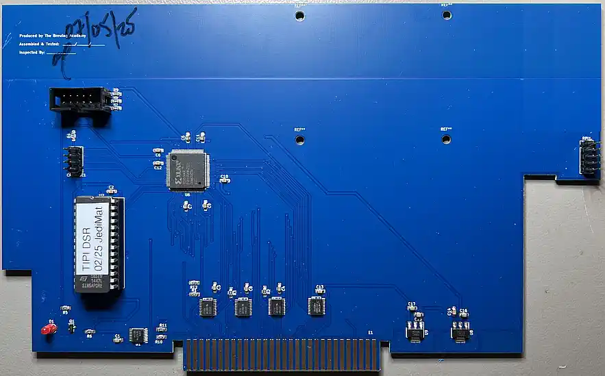 | ||
Grumpy soldering | |||
|
From above, as already described, the soldering of the components is perfect. Not so on the bottom... Here there was probably strong work with fluxes, and no one found it necessary to take the dirt down again. This is not appropriate, given the price tag (or am I "too german"???). No matter - you have Kontakt LR in the house... A few examples: 
 |


| ||
Power supply | |||
|
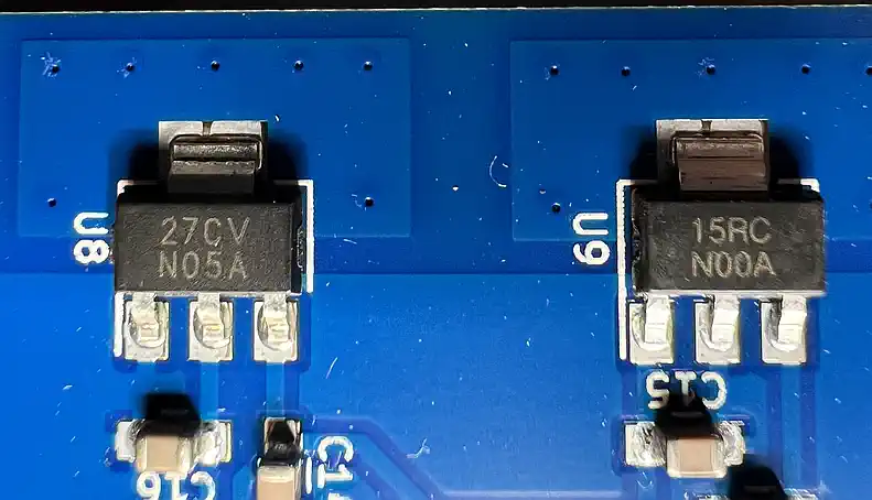
As already indicated above, there are 2 power supply networks - 5V 0.5A from a 78M05 in the SOT-223 housing (in the picture right), and 3.3V 0.8A from an LM1117 (picture on the left), also SOT-223.
Divergent to the original schematic by the way, where a 7805 in the TO-220 (1A) is provided. But that is not the only deviation from the original. A supply for the RasPi is not wired, but probably technically possible, as the following train of thought shows, taking into account the maximum current consumption: EPROM 25mA LED 10mA HCT138 50mA Pi3B+ 500mA (low CPU load, 400mA when idle) (Pi3B 300mA comparable load, 250mA @ idle) ---------------- Sum 585mA (385mA - 3B)The supply of the RasPi 3B+ is therefore not within the range of possibility if only this IC is used - a 3B would be OK - or a replacement of the 78M05 for the 7805 provided in the original layout. |
 | ||
Mounting and connecting the Pi | |||
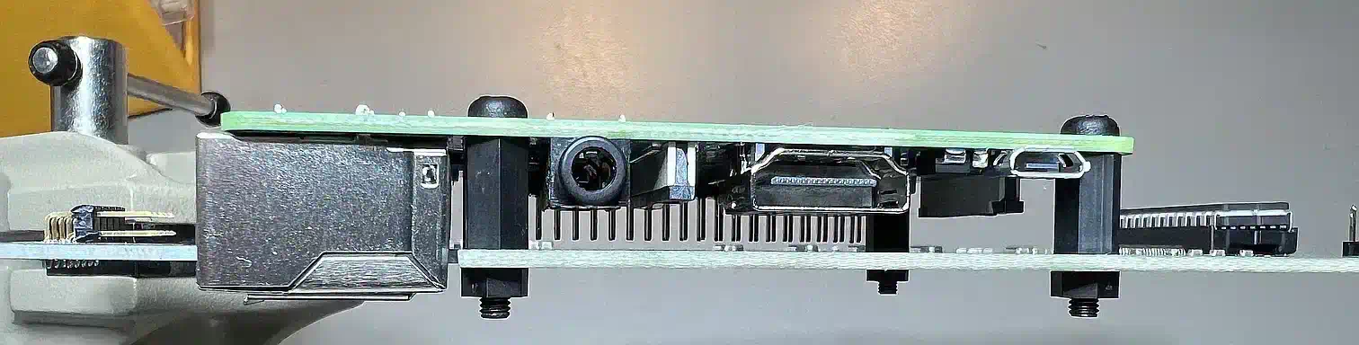
|
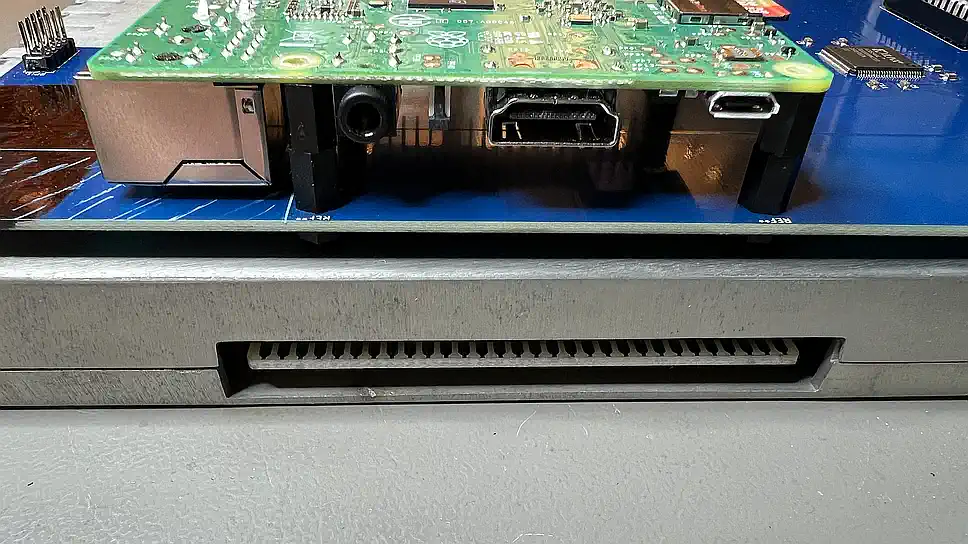
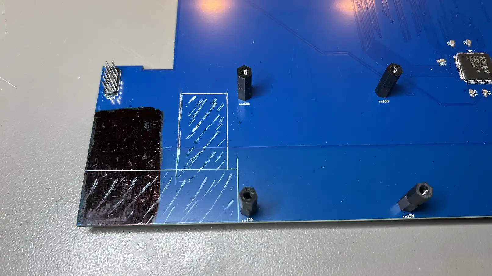
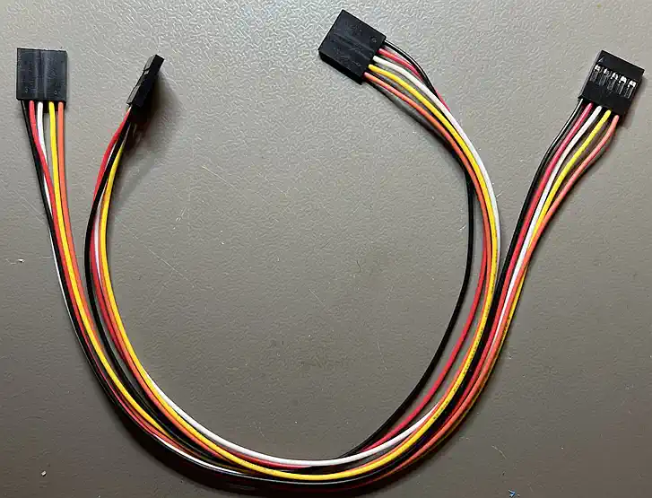
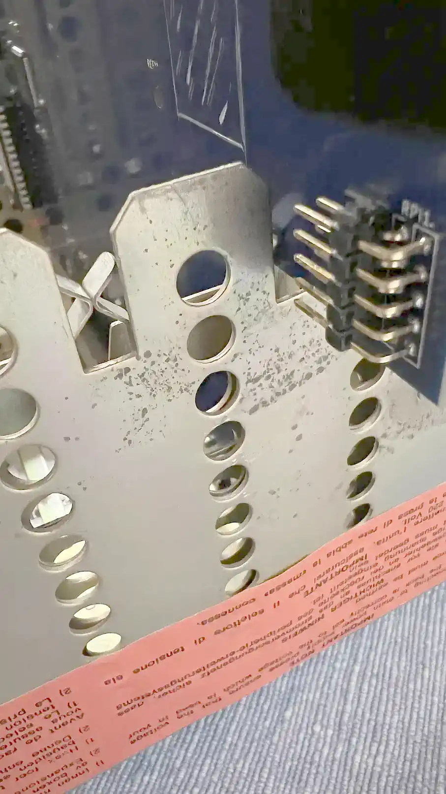
Due to their sheer length, the supplied cables already suggest that the RasPi is better placed outside the PEB, and the pin block for connecting the RasPi is also outside the PEB. This is OK for a Zero2W, because of Wi-Fi and the like. But I want to have that thing inside, and this creates another problem: From the top edge of the board of an RS-232 card to the outer edge of the case it is 13mm - from top edge TIPI-PEB board to the top of the Pi (solder side above!) it is 17mm! No matter how you literally twist and turn it - having the Pi in the PEB means mounting it through the board! From the pictures you can see how scarce it is compared to an RS232 card, and what it has to be sawed off from the board. I am only considering the LAN port - I don't need the USB ports (if you wanted to use them, the above electricity requirement calculation would anyway be unusable and already the RasPi 3B (without plus) would have to receive a separate power supply!). What you can't see are the tracks to the connector block, where the RasPi has to be connected - it also passes by extremely short of that. And of course, have the terminal pins to be replaced with the angled variant, otherwise the connectors are to blame if the height is not sufficient again? Nope, because then the clamps for the shielding will not pass the cables... in the end we have to solder them!? But - please - can someone tell me about the joke with the LED placement??? |
| ||
Lay him low... | |||
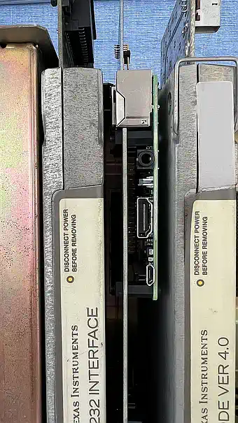
|
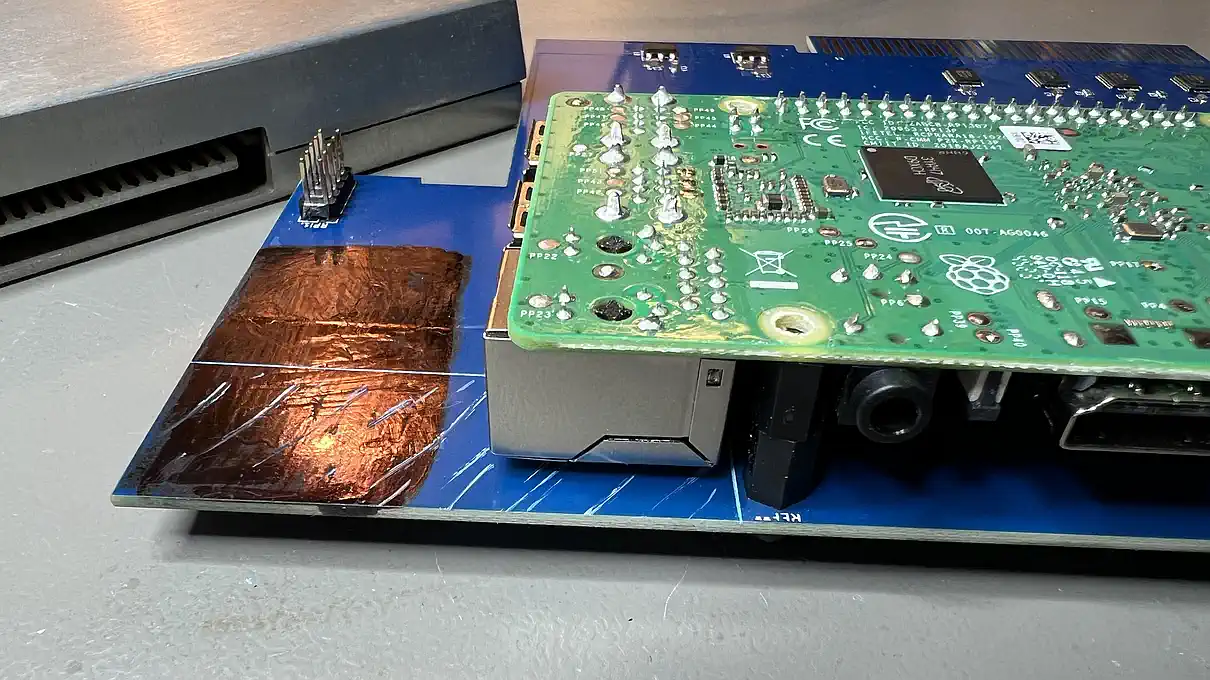
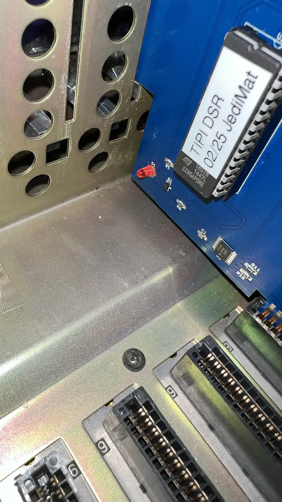
After a lot of sawing, drilling and filing, the RasPi was exactly where it should be. You can see quite well how he fits in between the cards, and doesn't block any space for other cards. I'm satisfied... ... however, the connection to the PEB must now be soldered, at least on the RasPi, but that should not be a problem. |
| ||
Which Pi would be best? | |||
|
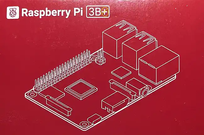
Tricky question... In the PEB you can use all variants of the "normal" RasPi up from 3B (3B, 3B+, 4, 5) - with the small form factor only the Zero 2W remains, but it has no connection for a LAN cable, and a TI with LAN connection - that's cool, isn't it. My very subjective recommendation goes to the 3B (no plus). Why? The computing power is comparable to the 3B+, because the requirements for the pace of work when used as TI-99/4A "secundant" are easily fulfilled, and the power consumption is significantly lower. ... besides, it is a little cheaper, and on its cover stand in large friendly letters...
oops - different book! |
 | ||
Proceedings | |||
|
The proceedings have not yet been translated - please see the german version for some impressing (me thinks) snapshots! Spoiler: it works great, but shows some weird incompatibilities with some weird software implementations, but TIPI seems not to be blamed... | |||
| Contact: {anyname}@{use_the_url}.net |
All pictures on this whole website were made by myself. Should you find them elsewhere, they're stolen from here! |
Last updated: 2025-09-17 CW |