 |
 |
|
|
 |
|
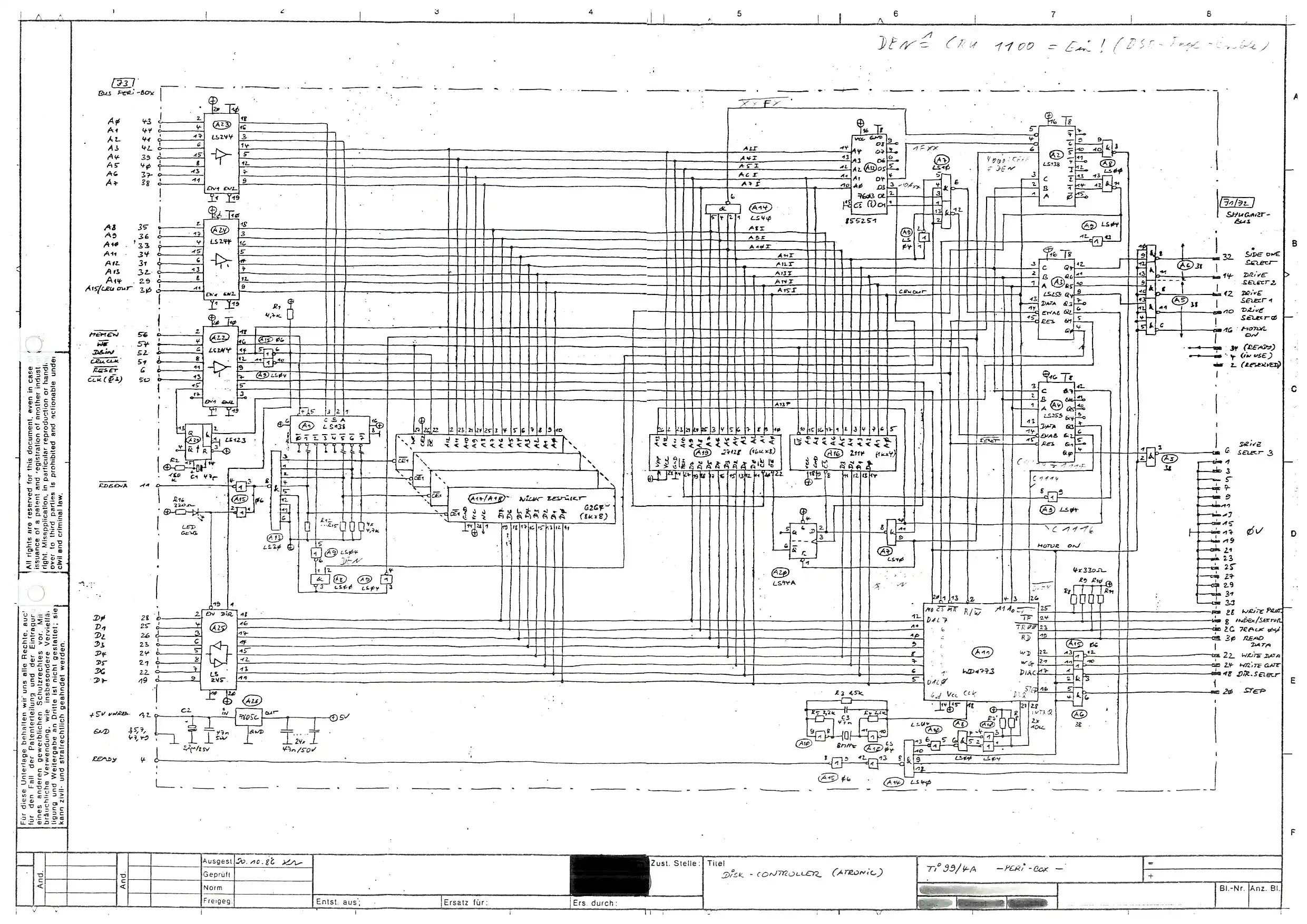
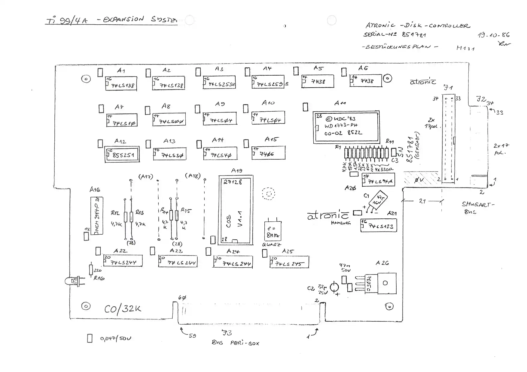
The Atronic Floppy Disk Controller is, what you nowadays call an "exotic item". The low circulation of this hardware makes it difficult to gain documentation of any kind (such as Circuit Diagram, Components Layout, etc) - not to mention any kind of information about modifications... (Since it is part of the Atronic CPS99, there is an alternative source for some background information.) During my active time with the TI-99/4A, this unit was THE ONE, although the DSR V1.1 had some issues, which never stroke me in the past - for whatever reason... Their removal will be the topic of a separate software project. My first FDC was a Myarc DDCC-1, initially connected to a Pertec DS/SD drive, which was soon replaced by two 2 Philips X3132 DS/DD floppy disk drives. Now DS/DD was possible - but only DD in the Myarc homebrew flavour, which was 320K instead of 360K per DS/DD disk! I only later discovered. that this is either considered being an adaptation of ECMA-70, described also the WD 1770 datasheet, or the so-called Hexbus Format, or something coming from the IBM 8" disks. I don't care, because why do you call it double density, if it doesn't provide double the storage space?!? (OK - to be fair, it WAS ECMA-70 conformant, but at this time all the PC world already adopted 18 SPT, so why going back to Bedrock City?) After becoming fatigued with these and other Myarc 'imponderabilities', the search for an alternative unit started, and that's where the Atronic FDC entered the play. By the way: This was the beginning of the ensuing, sustained aversion to Myarc products, and this aversion was confirmed every time a new Myarc product was released! But enough of this Myarc bashing - lets now dive into something completely different: the upgrade of the Atronic FDC! | |||
32K RAM for the FDC | |||
|
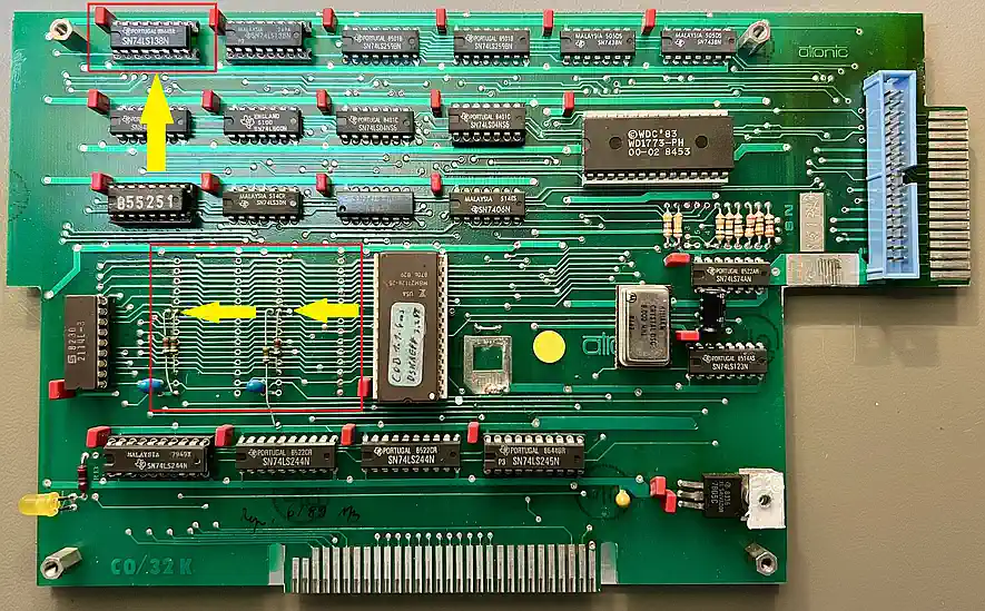
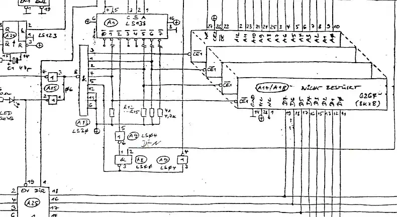
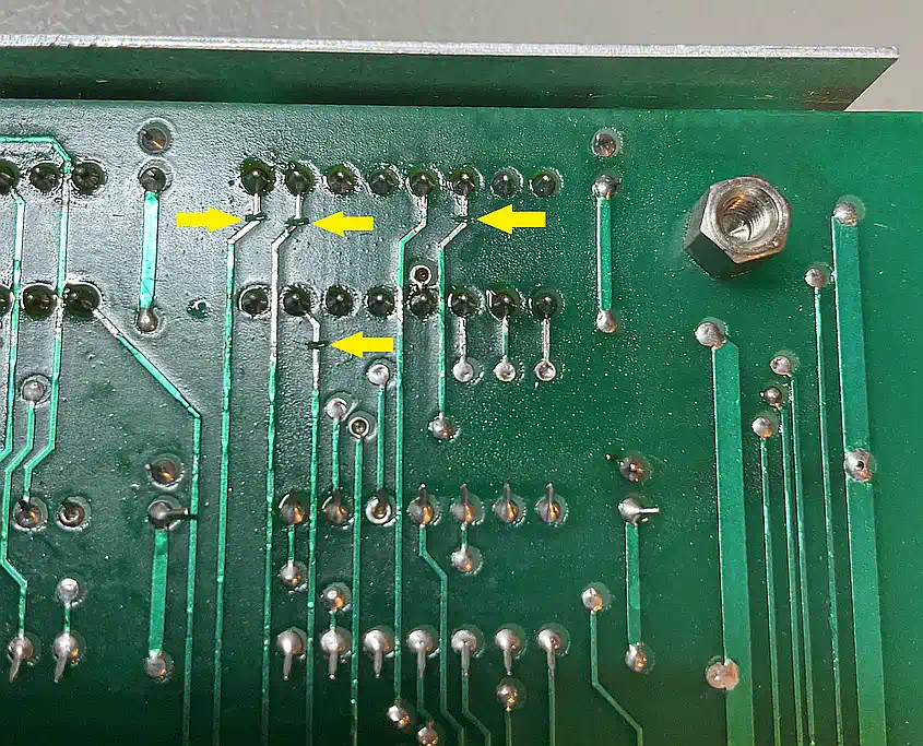
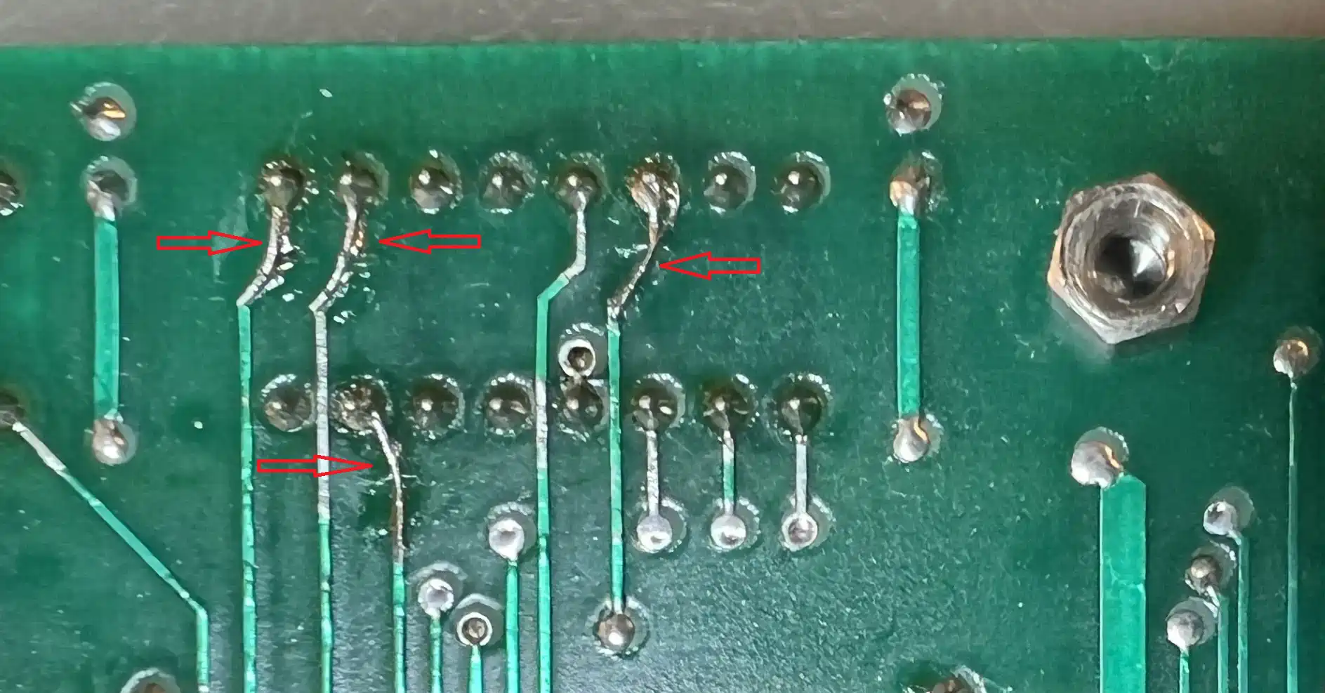
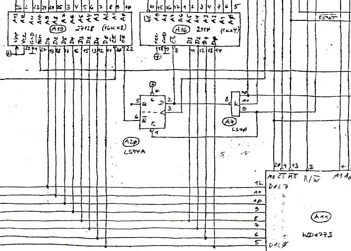
It is just logical: Atronic provides their own Disk Manager on diskette together with the hardware, which can be started with CALL MANAGER (or CALL MGR) from the BASIC commandline, and which requires a 32K memory expansion - well, why not provide it already on the FDC? Eventually, the TIPI sidecar does it nearly the same way, more than 30 years later. As one can see in the schematics, and on the backside of the PCB, the enable lines for memory blocks 1, 5, 6, and 7 (just those of the 32K memexp) are cut open and have pull up resistors to 5V, so the decoding logic sees them permanently inactive. It is therefore suffcient to re-connect the lines, remove the pull-ups and solder in 2 pairs of piggy-packed 8K SRAMs, using - for sure - separate CE lines. As an important side note, it is good to know that none of the signals related to the 32K is routed through the PAL, so don't expect conflicts resulting from a PAL that may be different if the same PCB is used as a 32K board (Atronic did sell them as 32K only). |
| ||
8 Bit System-RAM 2114 | |||
|
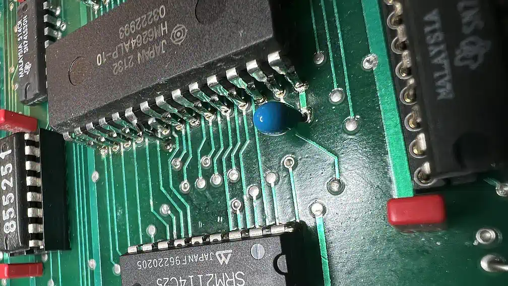
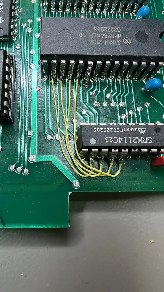
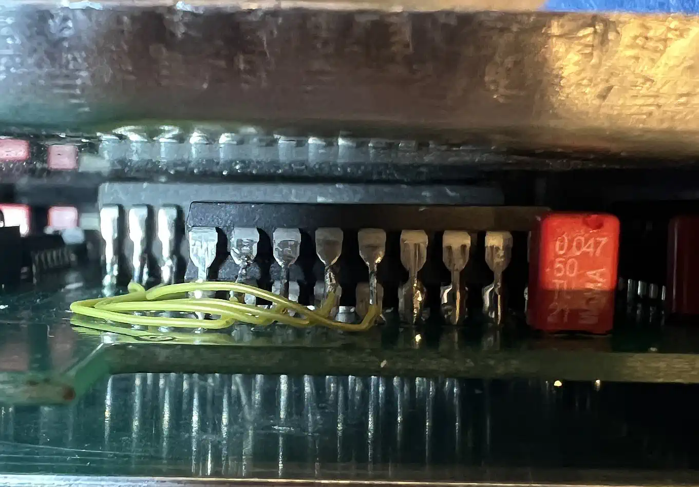
If you consult the ROM listing of this controller (or any listing of those FDC, that provide a system RAM), you may break out in tears facing
all this bit shifting because of the 4 bit wide data bus of the 2114. Considering a DSR redesign, this hardware modification seems essential - and it is by far the simplest one! Unfortunately, the built-in 2114 chip must be removed, including its socket, since the shell for the PCB doesn't provide enough height for socket plus 2 chips stacked on each other - all pins of the RAM chips besides the datalines must be soldered together. The 4 new datalines must be connected to the nearest datalines D4-D7, to store complete bytes. The DSR does not need to be adapted to this, since the annoying bit shift may remain for the time being... |
| ||
2114 - the story about the sesame and the 40 thiefs... | |||
|
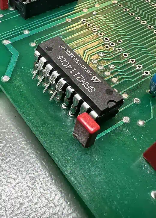
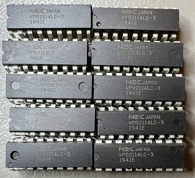
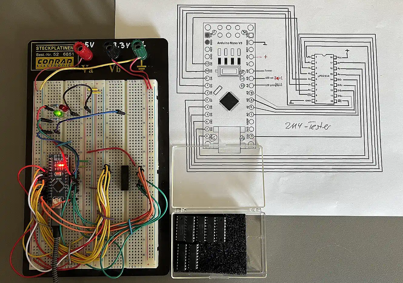
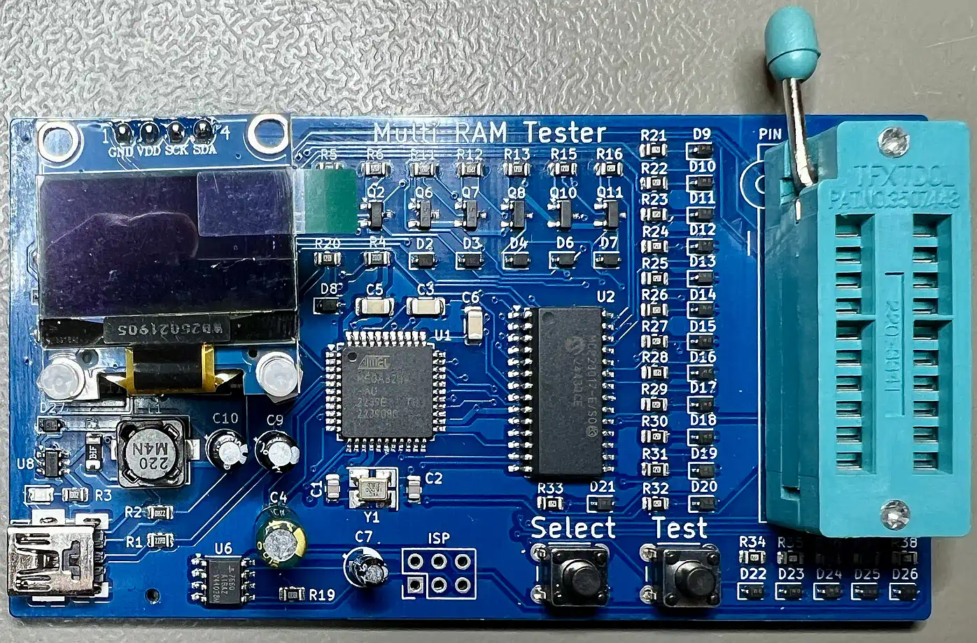
Where do you get those chips, which nowadays no longer play a role in modern circuit design? Look at Aliexpress, where you can still get them in any imaginable state and price. My policy with this "warehouse" is to keep my financial involvement as low as possible, and since the prices differ massively from eBay, where you encounter vendors that consider some powers of ten - compared to Aliexpress - is worthwhile for the "antique" parts, I ordered 10 of them for about 50 Euro-Cent each. Well - "you get what you pay for...": I received 10 completely different DIP18 enclosures, with sanded-away original prints and new and sluggishly laser marked "NEC Identity" (Image to the left - look precisely!). To determine, which of them really were 2114 chips, I was in need of a tester, in my case the Arduino Nano based 2114 Tester by Gordon Pimblott. Just out of curiosity I uploaded the Gerber files to JLCPCB, where I ordered 5 PCBs (minimum amount) incl. shipping for less than 5 Euro(!). Since a faster delivery with DHL Express would have cost me 25 Euro, I selected the cheapest one, which is sponsored by JLPCB on the first order, and already includes VAT and customs! While waiting for the PCBs to arrive, I pinned a prototype onto a breadboard (Image to the right - Nanos I have plenty in the maker drawer...) and tested all of them, and guess what - surprise: only 2 of the 10 were not what they claimed to be! While building the tester, and modifying its software (the timing for the RAMs in my opinion was too relaxed), I discovered the enormous power of these little microcontrollers, if you program them bypassing the hardware abstraction layer - but this me be a reason for a separate software article... Well - eventually I ordered a set of original EPSON RAMs on eBay - to avoid possible unrest... but currently everything works fine! The remaining RAMs and also the 4 remaining tester PCBs are to be given away. ... and then the Coca Cola Man delivered a universal "Vintage RAM Tester", that allows me th test the complete box of my vintage RAMs... but also this is a separate story. |

| ||
The Empire strikes back... | |||
|
The attentive reader may have noticed already: this 32K memory expansion is handy, simple to implement, but it cannot by the final word!
Why? For sure, the real TI freak needs a 16 Bit Memory Expansion, and if this one here is active together with the console built-in variant,
some chips somewhere may not be in Kansas anymore... The solution is simple: a lot of CRU bits on the FDC are not used, and are usually reset to logical LOW when a RESET occurs. Also, due to the crystal oscillator IC, there are some free LS04 inverters that you can use to generate an inhibit signal for the 32K on the FDC. You just need a OR gate with 4 systems and 2 inputs each which locks the 4 previously re-connected bank select lines to HIGH, thus disabling the 32K by default. Now the power-up part of the FDC DSR can check existence of a 32K, and - if none was found - can activate the one on the FDC. This will be part of the new DSR - stay tuned! Oh, yes - the new DSR... nearly forgot. You may occasionally look for the software projects... | |||
| Contact: {anyname}@{use_the_url}.net |
All pictures on this whole website were made by myself. Should you find them elsewhere, they're stolen from here! |
Last updated: 2025-10-21 CW |