 |
 |
|
|


 |
|
Looking at the datecodes of some components, this power supply seems to be more than 40 years old. You would expect that at least the electrolytic caps have gone bad over such a long time...? Well - wrong assumption, as it will soon show. But that's not the reason for amplifying the supply of regulated voltages - it's merely this: The PEB should receive a TIPI-PEB, and its Pi 3B+ would like to swallow a decent 2.5A for itself (pretender as he is, 0.5A will suffice) - but using a separate plug power supply is out of the question! | |||
Tabula Rasa | |||
|
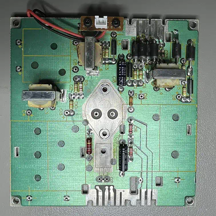
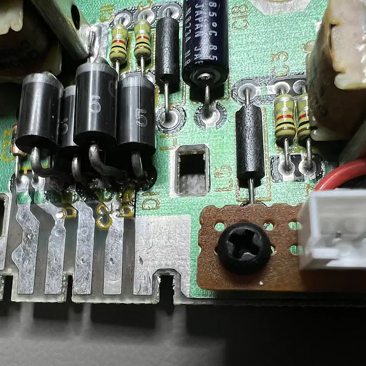
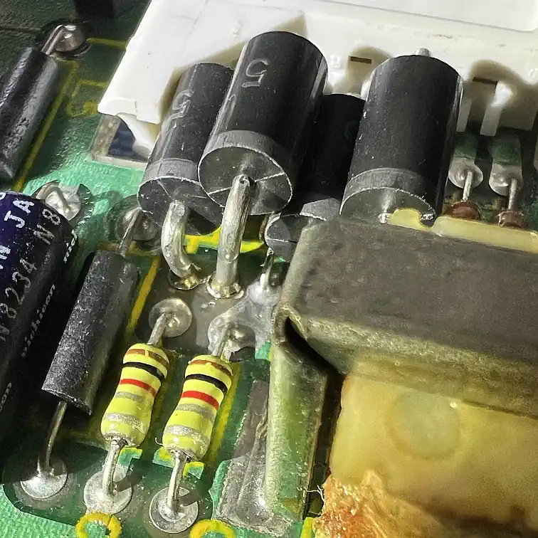
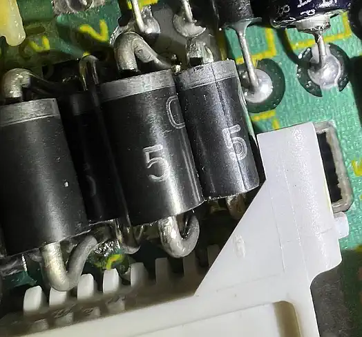
First of all, everything has to go that is planned to be replaced, which are the caps, diodes, regulator ICs... (The picture has the diodes already replaced...) If you're going to remove the components using a desoldering reworkstation, your better now replace the tip by the one with the larger hole - at least when you get to the 1N5401s, where to common 1mm tips will not work best. The small PCB with the plug, by the way, belongs to the project "Silent PEB". |
| ||
The voltage regulators | |||
|
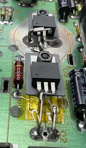
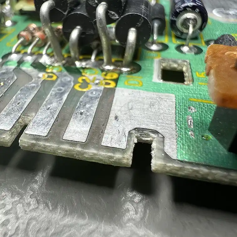
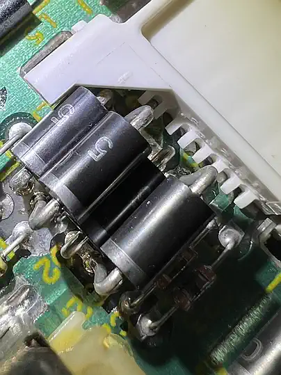
The 5V regulator for the floppy drives has to be replaced by a more powerful one. A simple 7805 will deliver max. 1A (and the original PCB has already heavily been cooked as you can see), so there will be a LM1048 IT5.0 rein. I don't care about the low-drop feature, I just want the 5A current!. And since we are already there at work, the TO-3 12V regulator (1.5A max) will be replaced by a LM1085 IT12, surging max. 3A. Pity, that the pins are all somewhere else... but as usual: a slice of kapton keeps the vampires out (or the like...). |
| ||
The electrolytic caps (really?) | |||
|
There are rumours, that electrolytic caps are always to be replaced if they have reached a decent age... WHO SAID THIS? Well, I thought, why not?! But Harvey said: WHY? Are they really dry/dead/gone? I'd better check and - maybe - learn. So - where is this component tester... oh yes - let's do it the engineering way: measurement first! And what should I say? They're up and running and by no means dry or dead! OK, admitting a slight capacity loss within the tolerance band, with only the 1000 microfarad one being out of it - I was surprised! Anyway - ESR and voltage drop makes the new ones the winnner, so: better get rid of the old stuff! Note: 1.2 Ohms of the ESR are caused by the workbench cabling - making the old caps even better... |
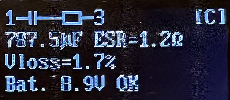
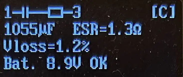 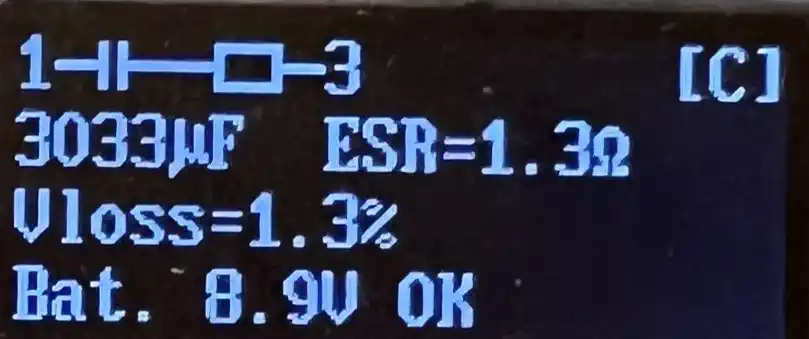
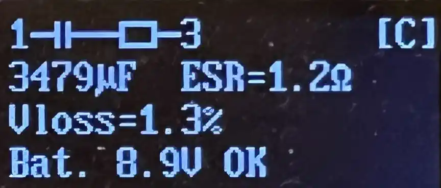 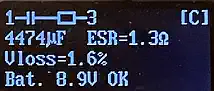
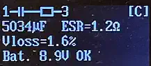
| left column: old cap right column: new cap |
|
The diodes | |||
|
Drawing more current through the regulators requires more current from transformer and rectifiers - so also the diodes need an upgrade. The weak 1N4002 anyway were a risk (and already replaced...), but the powerful 1N5401?Who cares - get them out! The new BY 550-800 have 800V blocking voltage (100V are needed) and 5A - should be enough. BUT: their respectable diameter makes it necessary the carefully consider the availble space so that the connector still fits! | |||
| |||
... and what about the transformer? | |||
|
So - if all of the semiconductors can supply BIG current, where does it come from? Relevant question - that's the weak point of this endeavour - I didn't find any reliable information about the power of the transformer on the secondary side (asking the common articial half-intelligence reveals useless fantasies, making me fear about the people that really take this for reality, such as rectifying the alternating current from the power supply in every PEB card...). Compared to a toroid core transformer with a similar volume, I rate this a 100-150 watts type, which would around 4A max on the secondary side. But what finally convinced me, was an accidential shortcut I did on the 20V rail - man, that scared me - this thing can fly! But should the internal fuse say "goodbye" there are some replacements ready. | |||
Done? | |||
|
Nope - measuring the voltages for the floppy drives was scary: 20% below nominal value! What's going on here - it is varying and instable?! Eventually, the too low voltage to the drives could be the reason for my floppy problems... or are they? Well - keep on reading... | |||
Corrosion! | |||
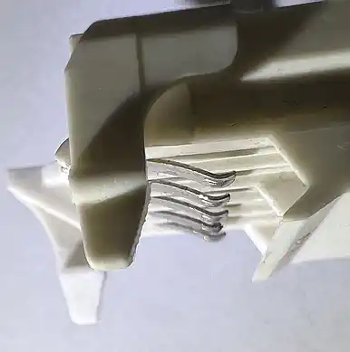
|
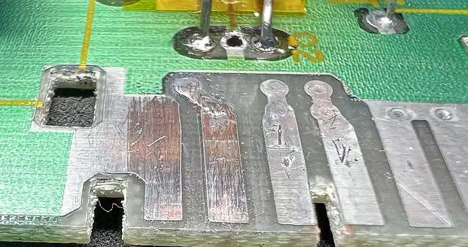
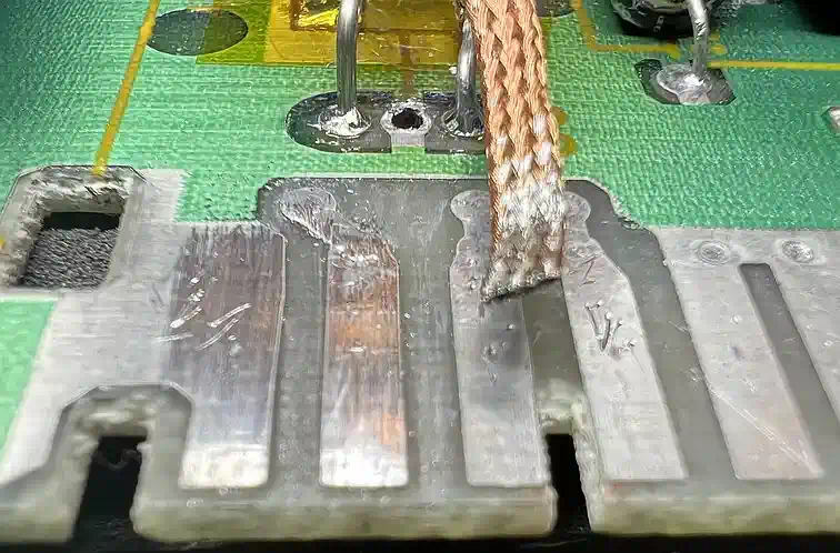
If there is something about the "ravages of time" for the PEB, then it will surely be the contacts from the PCB to the "outside" - not the caps, not the regulators. These contacts had developed a significant oxidization, and this explained the weird measurment results. Unfortunately I'm lacking the needed chemistry to find out if the surface did receive some kind of anti-oxidization treatment, but applying just a bit of IPA already removed some of the stain. And it's getting pretty if you use a bit of solder sucking wick as a grinding agent. Additionally recommended is to bend the contacts of the connectors towards the PCD to increase the pressure onto the tinned parts. The pictures may give additional hints... |
| ||
| Contact: {anyname}@{use_the_url}.net |
All pictures on this whole website were made by myself. Should you find them elsewhere, they're stolen from here! |
Last updated: 2025-09-22 CW |