 |
 |
|
|
 |
|
This very Mini-Memory I received from a snug member who migrated to USA - after nearly 40 years, the battery was flat, and a new one was needed.
And for sure, it had to be a 2430, so the next change would be far, and if a change was needed, it should be as easy as possible.
So, clearly there had to be a
battery holder - both of them could be acquired easily at reichelt. Of course, this required some adaptations, at the battery holder as well as at the module housing, and exactly these modifications are to be described here. For the sake of completeness, it must be mentioned that the whole effort could have been far less, if I would have been satisfied with a CR2032 - but I wasn't... | |||
The battery holder | |||
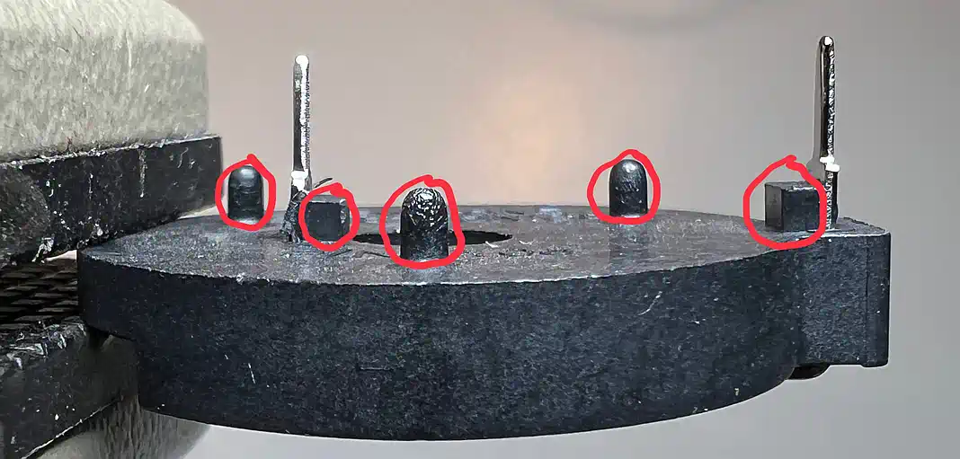
| If must lay flat on the PCB, and the clamp must not be raised. So it is essential to bend it flat, and the distance pins at the bottom have to be cut off precisely. |
|
||
|
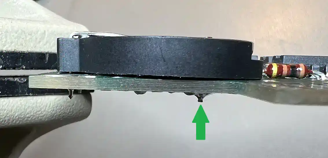
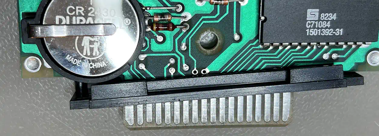
Since the battery holder has its ground (-) pin near the center (the + pin matches perfectly!), it cannot be connected at exactly the same spots, where the old battery was connected with a soldering lug.
Fortunately, right at the place of the holder's ground pin, there is a ground plane via!
Well, drilling a 1.3mm hole there was a breeze (there are more vias which compensate for the conductivity loss) and the holder could be soldered... BUT WAIT! Something's wrong! - flat is a different story. |
 |
||
|
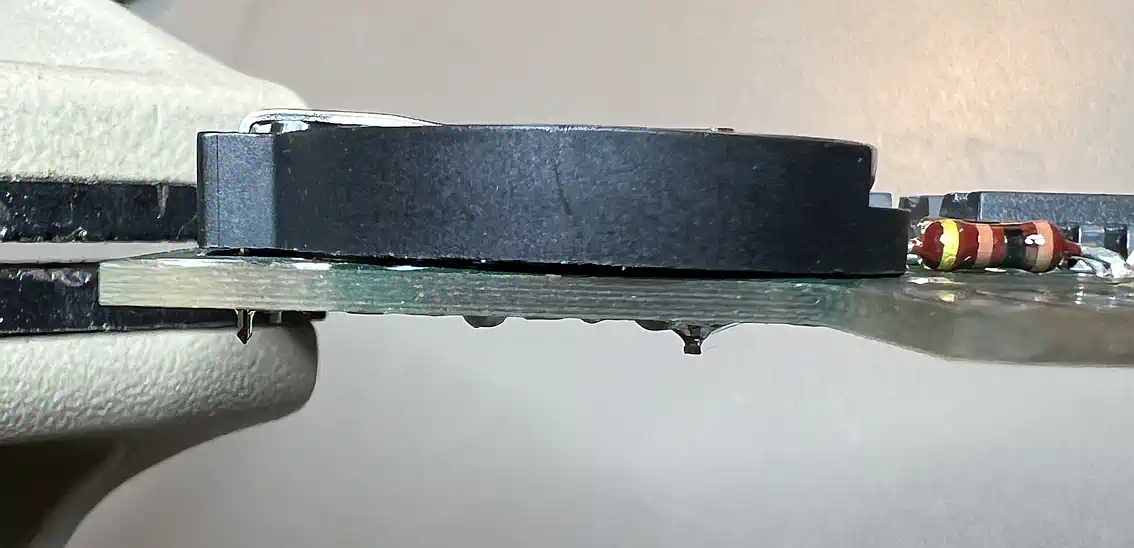
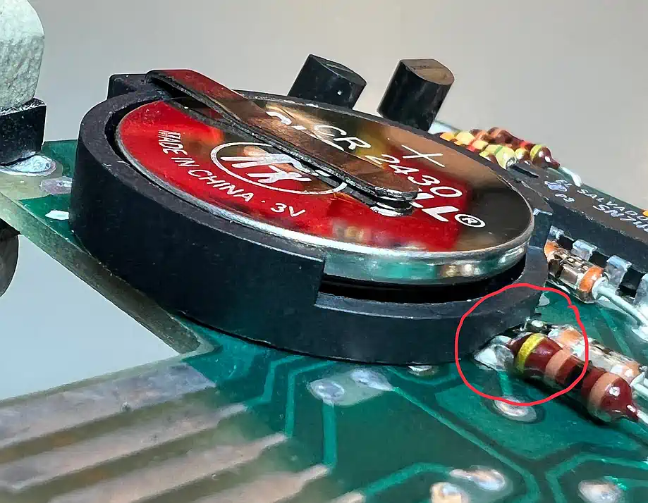
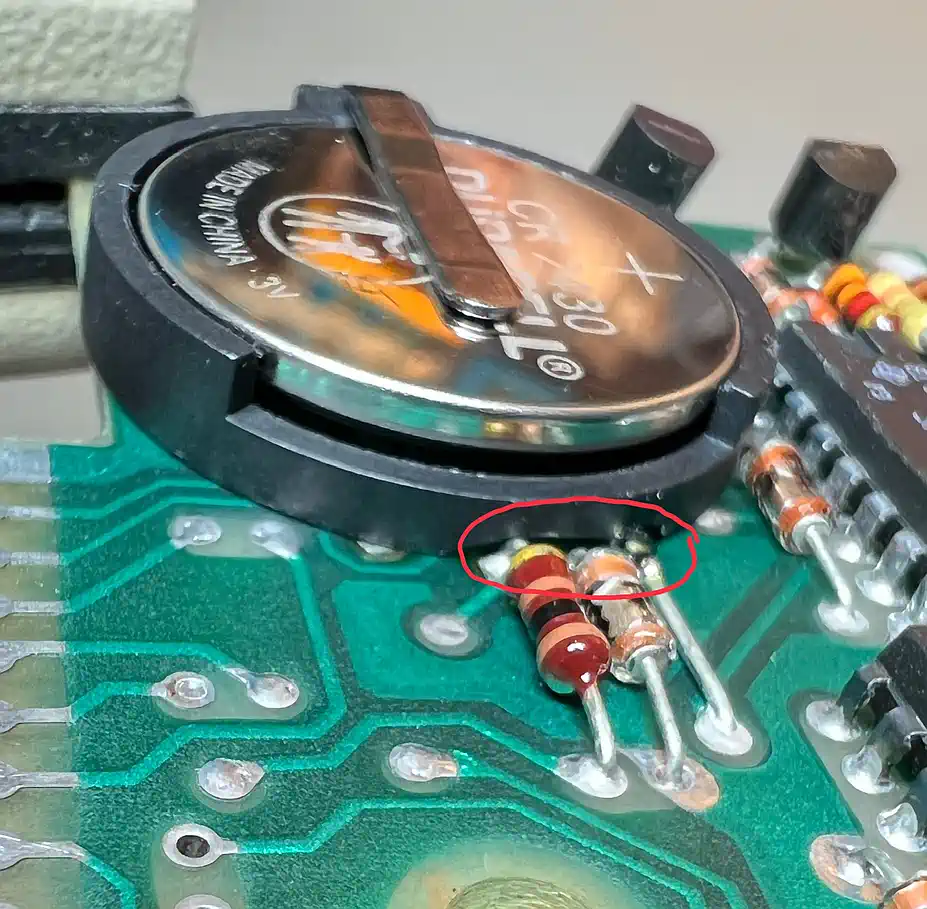
And, indeed, three components are in the way, and they rise the holder a bit - the lid of the case won't close!
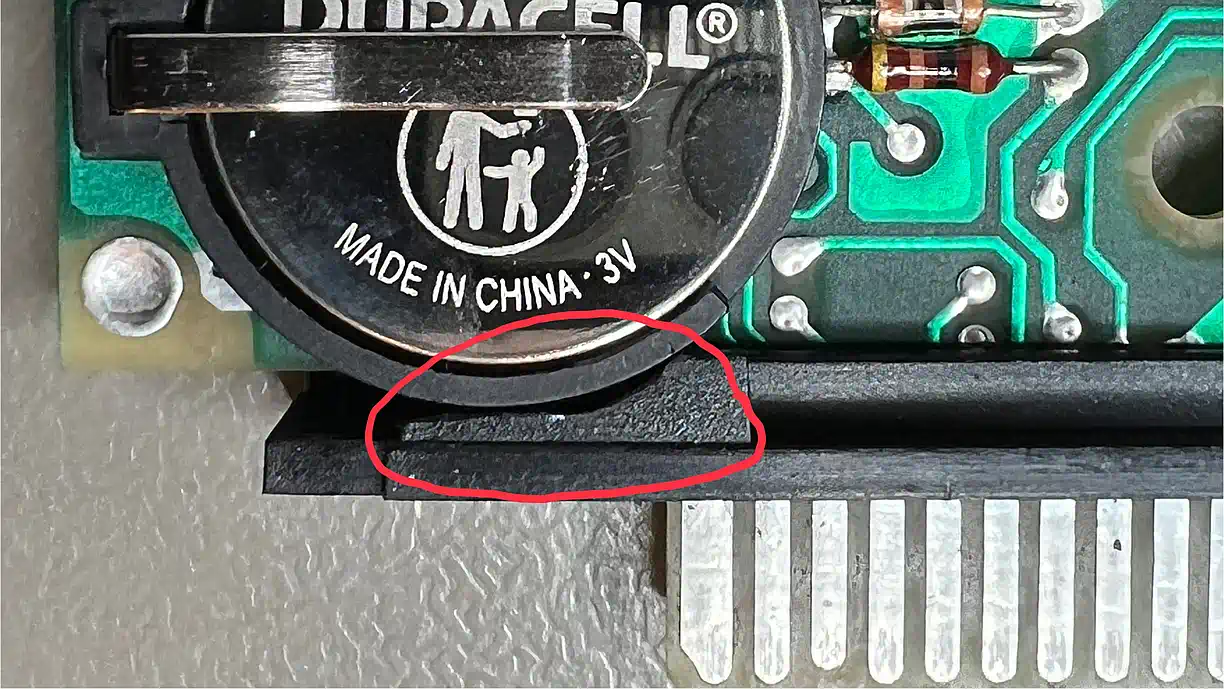
So, at the spots marked in red, the plastic has to be milled off a bit, to have the holder sitting really flat on the pcb. Now - done!? No - not yet, and as you can easily recognize on the photos, the battery holder protrudes beyond the board! |
| ||
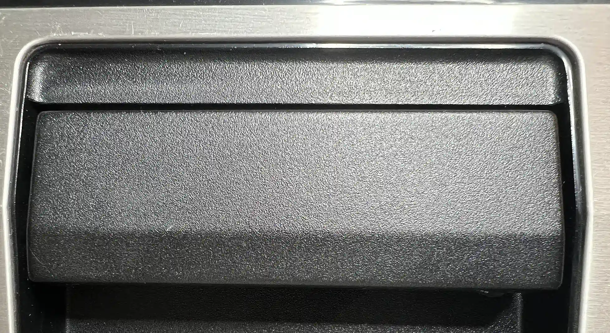
The port coverage | |||
|
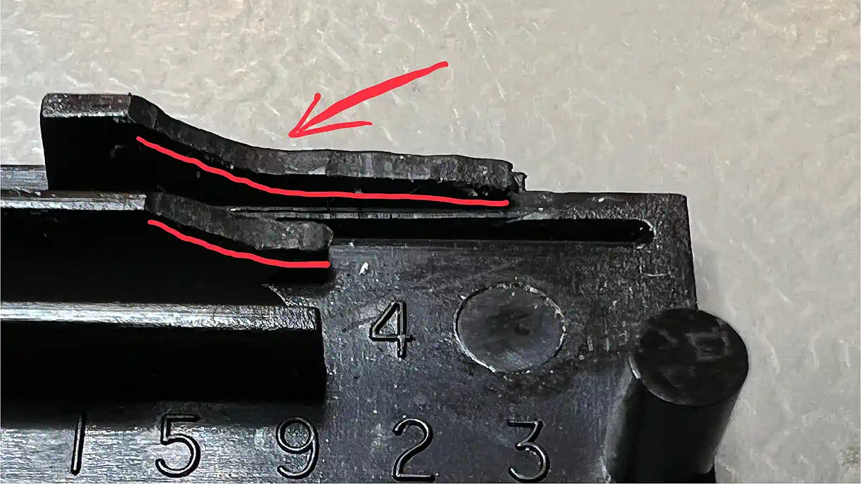
Well, the moment of truth came during assembly - where will the port cover go if the module has been plugged in?
It collides with the battery holder - Bummer! So - matter has to go, but be careful - exactly in this spot you find the spring which pushes the cover to the back and protects the pcb when the module is not plugged in. This guiding groove must therefore not be (completely) destroyed. As a hint, look at the red lines - and, while milling you should constantly check the match to the closing mechanism. |
| ||
The result | |||
| ... and this is how it looks like, after everything worked as planned: the height of the module allows to easily insert the module into the console's slot, and the the correctly milled bars of the cover allow parallel seating in the slot - Bingo! |
| ||
| Contact: {anyname}@{use_the_url}.net |
All pictures on this whole website were made by myself. Should you find them elsewhere, they're stolen from here! |
Last updated: 2025-09-17 CW |